5. Software Basics
Introduction
Writing a project is basically graphical flowchart editing. First click a flow node, then drag other flow nodes from the left side into the project, or press certain robot arm buttons to create nodes. The new node is automatically connected below the selected node. You can also click the × under a node to disconnect the next node, or manually drag a connection line to connect two nodes.
Coordinate Systems (Base)
The commonly used coordinate systems are:
- Robot Base: has an "absolute position" concept. Its coordinates always represent the same place.
- Vision Base: has a "relative position" concept. It is automatically created after each vision task and its origin changes according to the detected object.
- Tool coordinate system: usually only used with
Move. Its origin is the flange center, so normally its Z axis is opposite to Robot Base. You cannot create this coordinate system separately from the project page.
To change the coordinate system you are using, just use the dropdown menu in the upper-right corner.
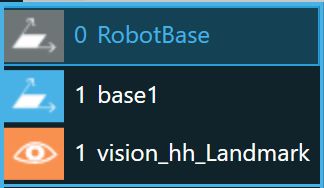
Common coordinate systems. The normal coordinate system in the middle is outside this textbook's scope.
Moving the Arm
Hold the FREE button on the robot arm, then pull the arm directly to the position you want.
For finer movement, click  at the top and use
 + and - on the controller for small adjustments.
Point
After moving to the position you want, first confirm that the coordinate system in the upper-right corner is the one you want. Then press the Point button on the robot arm or drag in a Point node in the software to record the current coordinate position.
Vision
Concept
Vision has two main types:
| Positioning | Inspection | |
|---|---|---|
| Editable tasks | Object positioning, TM Landmark positioning, servo positioning, object calibration, Smart-Pick | AOI recognition and visual I/O triggering |
| Creates a new coordinate system | Yes | No |
Note
A Vision (Positioning) task also has a Point function. In other words, it moves to the specified position before starting visual recognition. Before creating Vision, check that the coordinate system is correct, usually Robot Base.
How to Use It
In the basic course, we mainly use object positioning and Landmark to introduce Vision.
Whether it is object positioning or Landmark, both use a Vision node under Positioning. Move the arm to a suitable position first, then drag in a Vision node. After adding it, click the upper-left edit control to enter the editing screen. Click Select next to Vision Task, then click  to create a new vision task. Give it any name, then enter the vision task editor. Confirm that
 Eye-in-Hand is selected on the left and click Set, then follow the steps below to set up object positioning or Landmark.
Object Positioning
Click Object Positioning → Next. After it finishes running, you will enter the object positioning editing flow. The blocks on the left are the recognition flow. Set them one by one in order; it is not hard to remember.
In the first block (Motion), click Set Working Plane → Create → Yes to enter the working plane setup. On the Vision Application Selection page, choose Auto → Next. You should see the current camera view in the center. Put the calibration board where the camera can clearly detect it. It is recommended to place two or three mahjong blocks underneath so the calibration board stays level. Then click  →
→ Yes to enable lighting during calibration. Press Next, then follow the prompt and hold PLAY on the controller. The arm will run automatic calibration. When the progress bar is full and the prompt disappears, a "calibration complete" window appears. Click OK, give the working plane any name, then click Save → OK. After this step, you can remove the calibration board.
Next, click the Camera block on the right. It is recommended to check Built-in Light; it turns on the light during vision tasks and turns it off after recognition, which reduces failures caused by the environment. Click Auto Adjust Camera Parameters to finish this step.
When the Camera block is selected, a appears below it. Click it, find Pattern Matching (Contour Feature) under Find, select it, and click OK. Put one mahjong block in the image, preferably straight, so selecting the template is easier. Choose Select Template on the right. In the template selection window, drag a rectangle around the TM logo on the mahjong block. Avoid the small text below and the QR Code above. Click Next, wait for it to finish, then choose the template you think is most accurate and click OK. Important: after creating the vision task and before actually picking it up, do not move the mahjong block, or you will need to recreate the task.
Click  in the upper-left corner →
 Save → Yes to save the vision task. Finally click Yes → Set → Confirm to leave the vision task setup page. Done.
Landmark
Click Landmark Positioning → Next. After it finishes running, you will enter the Landmark recognition editing flow. Like object positioning, the blocks on the left are the recognition flow, but Landmark is much easier to set up.
Unlike object positioning, the first step does not require setting the Motion block, because Landmark detects automatically. Click the Camera block on the left, check Built-in Light (recommended), and click Auto Adjust Camera Parameters. Then click the final SUMMARY block. After confirming that a box appears around the Landmark, click → Save → Yes to save the task. Finally click Yes → Set → Confirm to leave the setup page. Done.
Case When Recognition Fails
After a vision task is created, the node has two branches below it: Found and Miss. They mean "object detected" and "recognition failed." The success case is easy: continue writing what to do next. For failure, the most common approach is to keep recognizing until it succeeds.
Use a Goto node. Select the Vision node, drag in Goto, and choose Lost Path; this connects Goto under the Miss branch. Then click the pencil on Goto, click Set Goto Target, and the screen turns gray with all nodes highlighted. Click the Vision node → Confirm, and Goto will loop back to Vision. After that, if recognition fails, it keeps trying until it finds the target.
Small Tip
As mentioned earlier, Vision creates a new coordinate system. After creating Vision, set Point to use Vision Base, and you can accurately control the arm to pick up or place the mahjong block.
Set
Set is powerful, but this chapter only explains how to use it to open and close the gripper.
Create
You can drag Set from the left side of the software, or create it with the SET button on the robot arm. Competitions may lock the button method.
Configure
To control the gripper, enter the Digital Output setting in Set, click Select on the right, and find DO_0 under the end module in the window that appears. This controls the gripper state.
There is a circle next to DO_0. Clicking it cycles through H, L, and blank. H means grip, and L means release. Pretty intuitive.
Click Output Test to move the gripper to the state you set.
Wait for
Wait for can wait for I/O, time, variables, and other conditions, but this chapter only covers the most common use: waiting for time.
Purpose
In basic projects, it is often used after opening or closing the gripper. Gripping and releasing take time. If the project speed is high, the gripper may miss or toss the object because things move too quickly. To make sure the gripper finishes before the next action, add a Wait for after the gripper action.
How to Use It
In the Wait for editor, choose Select next to Time. In the window on the right, choose the top option with an input box, usually the default, and enter the wait time. A common suggestion is 500, meaning 500 ms, or 0.5 seconds.
Move
Purpose
After operating the gripper, we often use Move to raise the arm before moving to the next point, so it does not hit anything along the path.
How to Use It
Usually we use the tool coordinate system for movement. Enter a negative value on the Z axis to move upward, such as -100, meaning up 100 mm, or 10 cm.
Stop
Stop is an ending node. It goes at the end of a project and automatically exits the project execution screen when reached. Since Stop represents the end, no node can be connected under it. It is not mandatory, but it is a good habit to put Stop at the end of every project.
Running a Project
Start Running
Press PLAY on the controller. The screen enters the project execution page, plays three beeps, and then starts running.
Control Speed
The row of lights under the controller shows the current project speed. The default is 5%. Use + and - on the controller to change the speed. Beginners should usually keep it below 15%, then raise the limit gradually after becoming familiar with the arm.
Return to the Controller
After execution finishes, if there is no Stop node, the software stays on the execution screen. Press STOP on the controller to return to the project editing screen.
Another case is when the project does not finish, whether because of an error or because it is stuck in an infinite loop, such as a wrong loop condition or a vision task that cannot find the target. In that case, you can also press STOP to stop and exit execution.
Common Errors
Causes and Signs
The robot arm may report an error after hitting something, or when a joint is pulled to its limit, also called a singularity. The arm light turns red and the software becomes gray and cannot be operated.
How to Clear It
- Hold
FREEon the arm and move it away from the original position, obstacle, or singularity - Long-press
STOPon the controller to clear the error state - Review and modify the project, confirm the cause, and fix it
Error as soon as it moves
If the arm reports an error as soon as it moves, but it can still move, one joint may be near a singularity, possibly because it has been rotated a full circle. Keep trying to identify that joint, manually correct it, and set the arm back to Standard Pose so it will not get stuck at that joint again.
When the error cannot be cleared
You can try the most primitive and violent method: reboot.
But try not to rely on this. Learn to find and solve the problem. If you cannot clear an error during competition, it may be counted as an unfinished run.